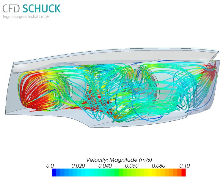
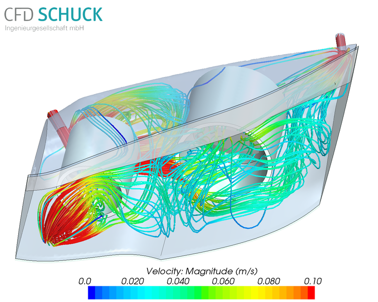
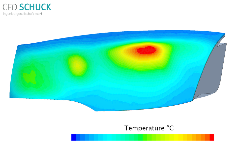
The video below shows the de-fogging process of the inner side of a head lamp used in common cars. Due to varying temperatures and air humidities in- and outside the unit, water may condensate on the inner surface of the lamp. For aesthetical and functional reasons it is necessary to either avoid the development of such a water film or reduce condensation quickly by means of efficient ventilation.
Computational Fluid Dynamics (CFD) can take on a major role in such a design and optimization process as turnaround times are usually faster and costs are lower compared to physical model testing. Thereby engineers quickly reach a state, which enables them to decide on the best geometry based on a large number of designs that had been simulated. De-fogging and de-icing are not only important in the case of the described problem, but also for the windscreen. By optimizing the air flow towards the windscreen inside the cabin, the sight of the driver may be improved and safety will be increased.
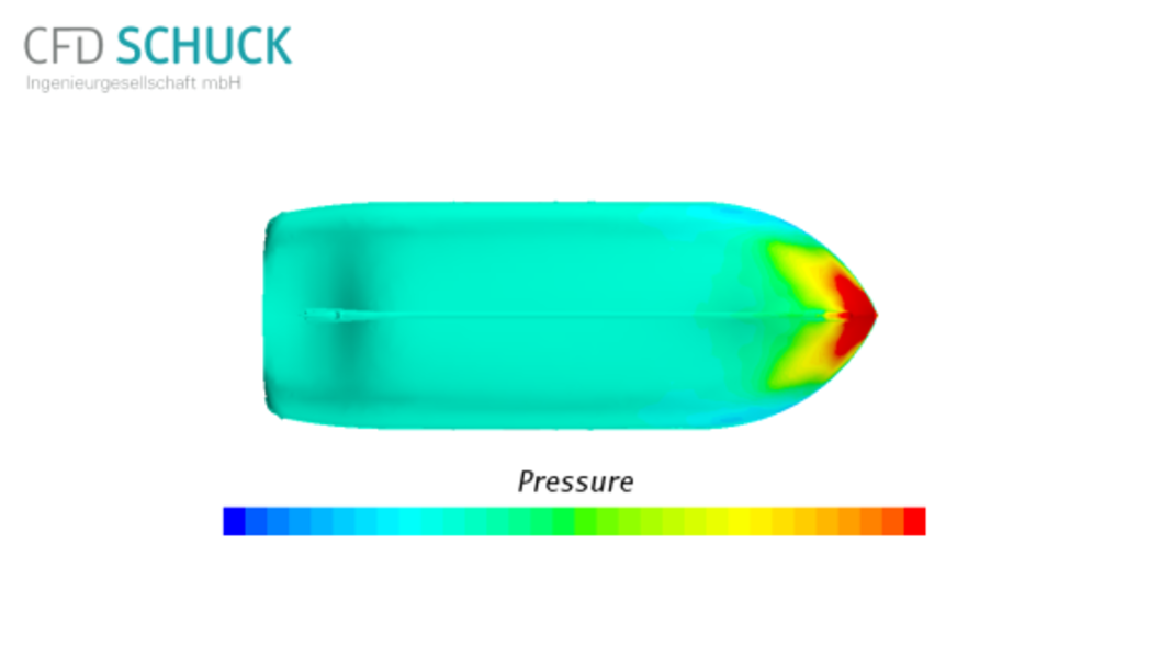
The video shows the impact of a lifeboat from a height of 15m into the free water surface simulated with Computational Fluid Dynamics (CFD).
This type of lifeboat, a so-called free-fall lifeboat, is mainly used on large container ships and oil platforms to quickly evacuate the sailors in a case of emergency. It is placed on a slide from which it is released and freely falls, often from great heights, into the water. The boat is closed and the persons are buckled into their seats to withstand the impact. It enters the water, submerges and stays underneath the surface for several seconds. For stability reasons and to provide maximum safety for the passengers it is extremely important to know the forces on the hull due to the impact. Furthermore, it is beneficial for a successful rescue, that the boat has covered the maximum distance from the impact area before its own propulsion engages.
The application of numerical methods in marine hydrodynamics, i.e CFD, allows for cost and time effective design optimisation of hull shapes and their mass distribution for various launching conditions, i.e. heights, impact angles and sea states.
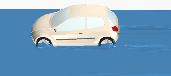
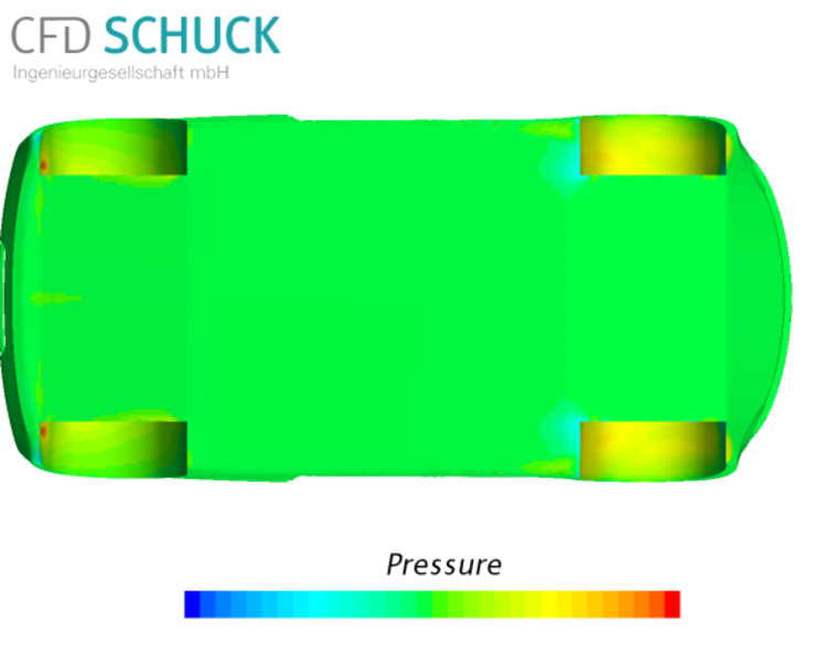
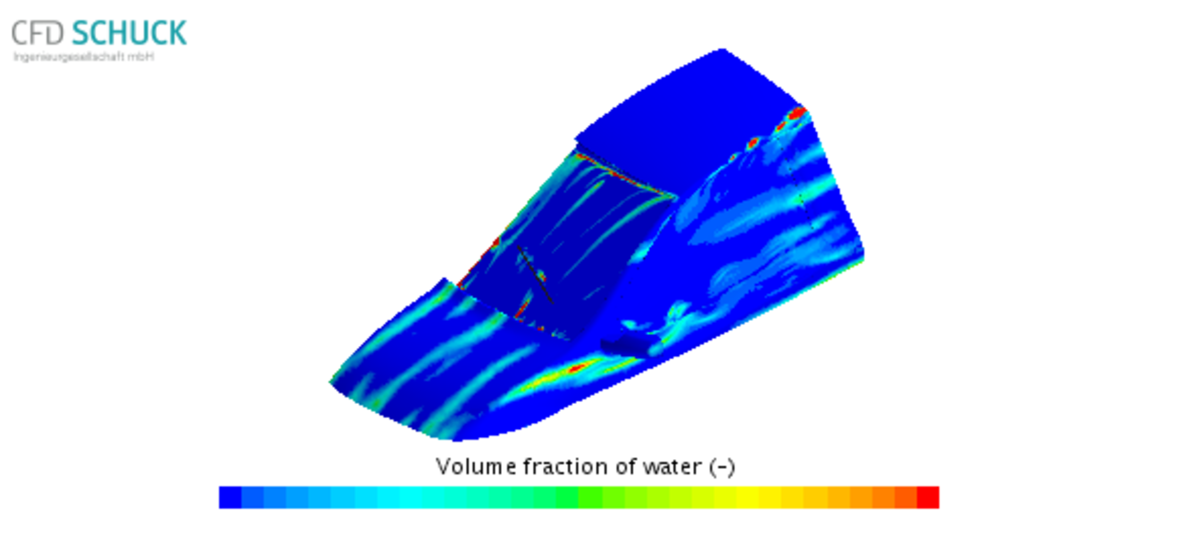
After heavy rain events streets may be flooded and the maximum wading depth of the car can be reached quickly. The wading depth of a car is the distance between the road and the air intake of the engine. Furthermore, even at low velocities it is possible for a bow wave to develop, which increases the risk of water getting into the combustion system. Apart from the above problem, the dynamic and static fluid forces on the chassis parts may be significant.
Computational Fluid Dynamics can provide valuable insight in the flow field around a car (water and air). Especially the fluid forces on the chassis parts due to driving through deep water and the critical water height in the engine bay can be predicted very accurately for different front-end designs and driving velocities.
The video shows the simulation of a generic car driving through water (car model DrivAer © Chair of Aerodynamics and Fluid mechanics, Technical University of Munich).
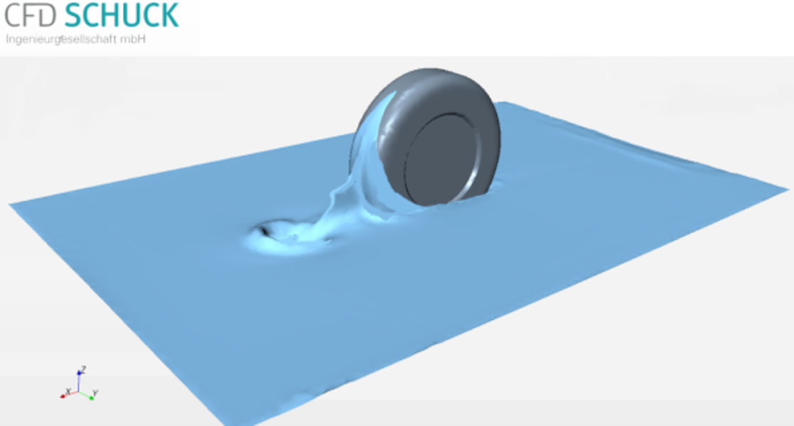

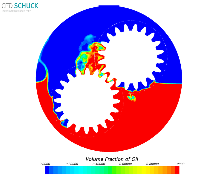
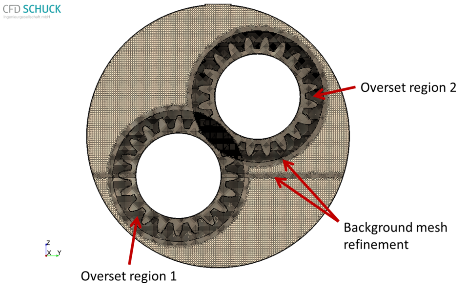
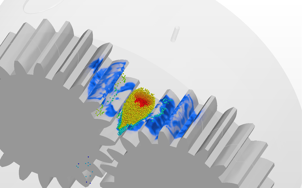
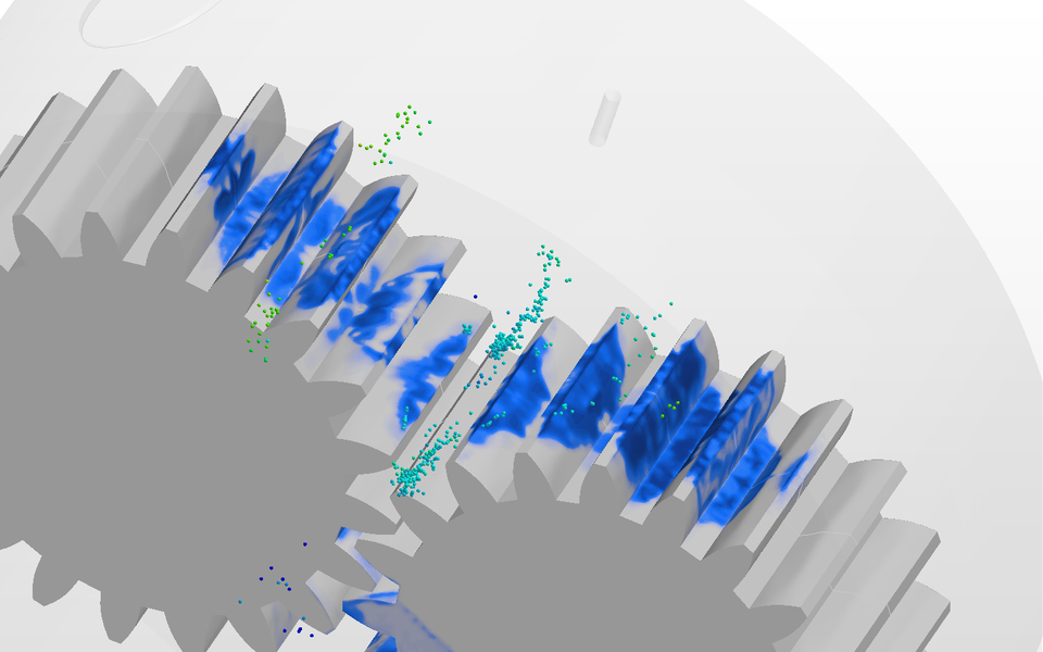
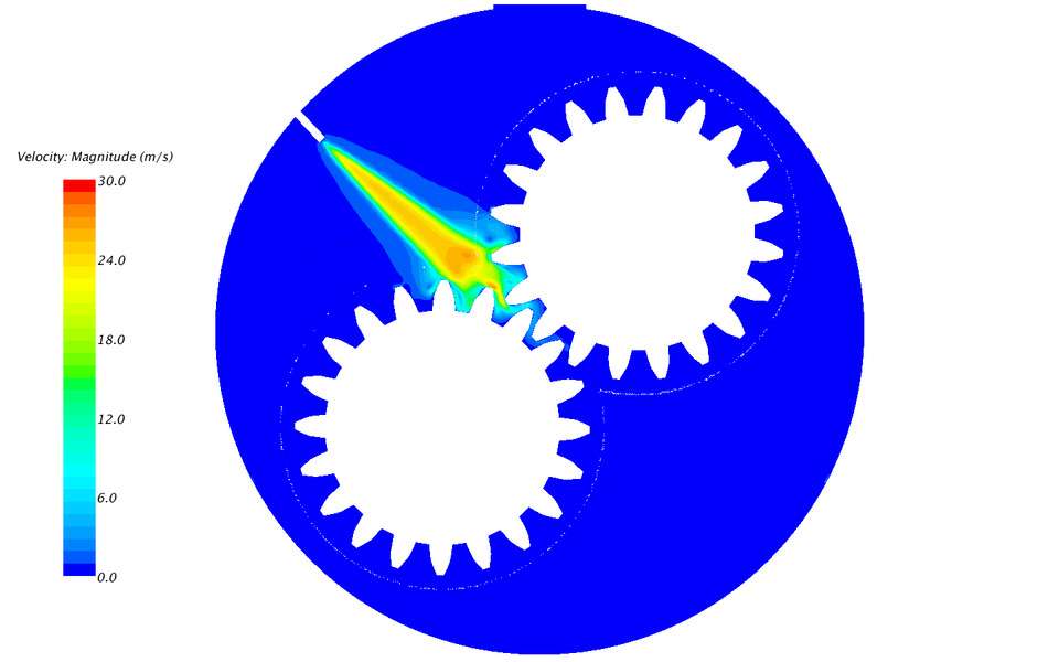
Problems which arise when gear lubrication becomes insufficient are well known by every bicycle rider as well as car driver. Replacement of bearings, pistons, piston-rings, and gearwheels is time consuming and expensive. Gear lubrication is a significant concern in a wide range of industries which use power transmission. However, prototype testing of gear-boxes not always provides the necessary detail information for complex modern gears often carrying greater loads with high rotational speeds. CFD model prediction is thus an effective tool for optimization of oil flow around the rotating components in a gear-box. The results of CFD simulations can help to improve the efficiency of transmissions, reduce the friction between the gearwheels (pitting), minimize load-independent spin power losses, and assess oil splashing effects on gear housing. The newly enhanced Overset Mesh technology which allows for multiple overlapping overset zones in STAR-CCM+ coupled with multiphase flow based on the Volume of Fluid method (VOF) offers the necessary simulation environment for dealing with such complex simulation problems as rotating gear systems.
More information can be found in our publications.


This video shows the CFD results of water spreading of front and side windows of a car driving (150 kmh) in the rain. A fast soiling of side windows of a driving car during raining conditions results often in obscured visibility on the exterior mirrors and this is a substantial risk for safe driving conditions. Not every new vehicle design provides best conditions for the car water management at the transition between front screen and roof. Some a-pillar concepts and mirror geometries are also not suitable for water transportation away from the exterior mirror area at the side windows.
Comprehensive CFD simulation tools allow a detailed analysis of the air flow around the car and of air vortex caused by the exterior mirrors. Water management can be simulated by different multiphase flow models like Fluid-Film or Volume of Fluid. In the example shown the coupled simulation of the front screen wiper movement allows a realistic representation of the water spreading during rainy driving situations.
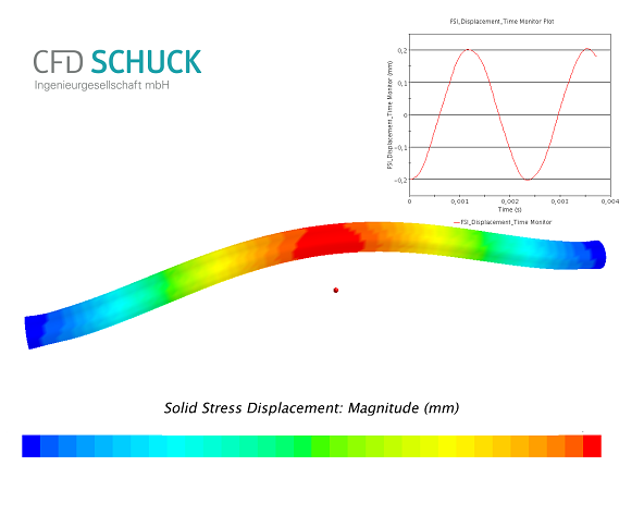
These days, fluid–structure interaction plays a major role in engineering applications such as aircraft, buildings and energy generation. Failing to consider the effects of oscillatory interactions can be catastrophic, especially in structures comprising materials susceptible to fatigue. An Example is the structural collapse of the Tacoma Narrows Bridge in 1940.
Due to numerical simulation the real behavior of a component or flow can be reflected exemplary. Useful methods are the Finite-Volume Method (FVM) or Finite-Element Method (FEM). Both methods are based on solving partial differential equations.
The following movie shows the interaction of a streaming tube and his material. In each time step the vibration of the tube is visible.
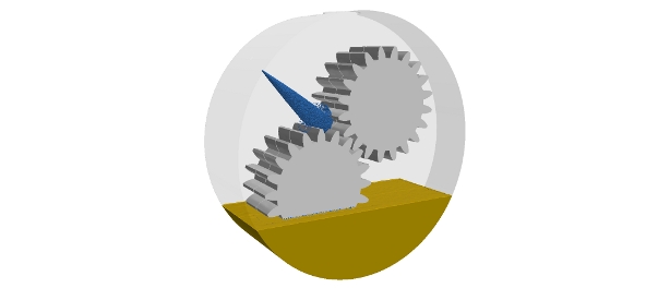
The aim of simulating spur gear systems is to minimize load-dependent and load-independent losses. Heat produced by friction should be efficiently extracted from the gear system.
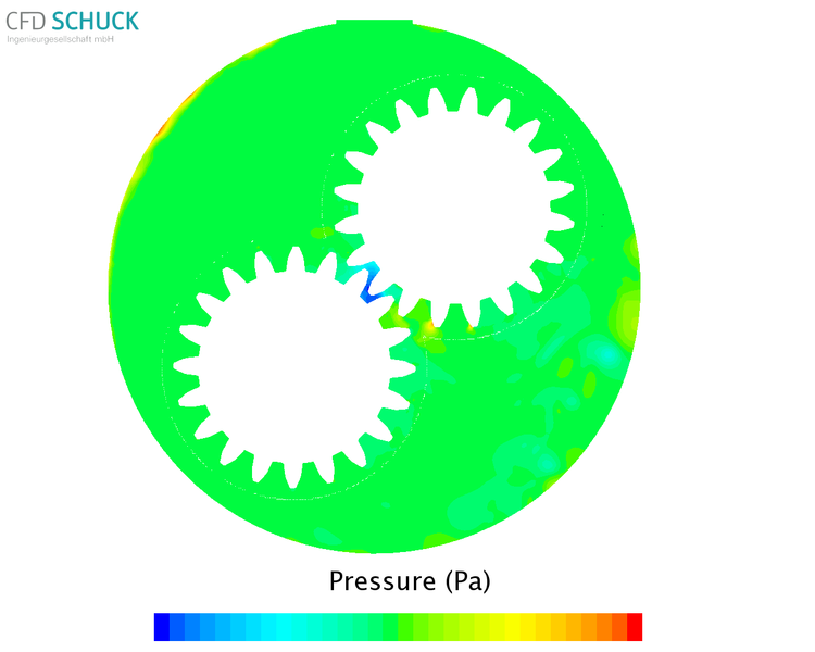
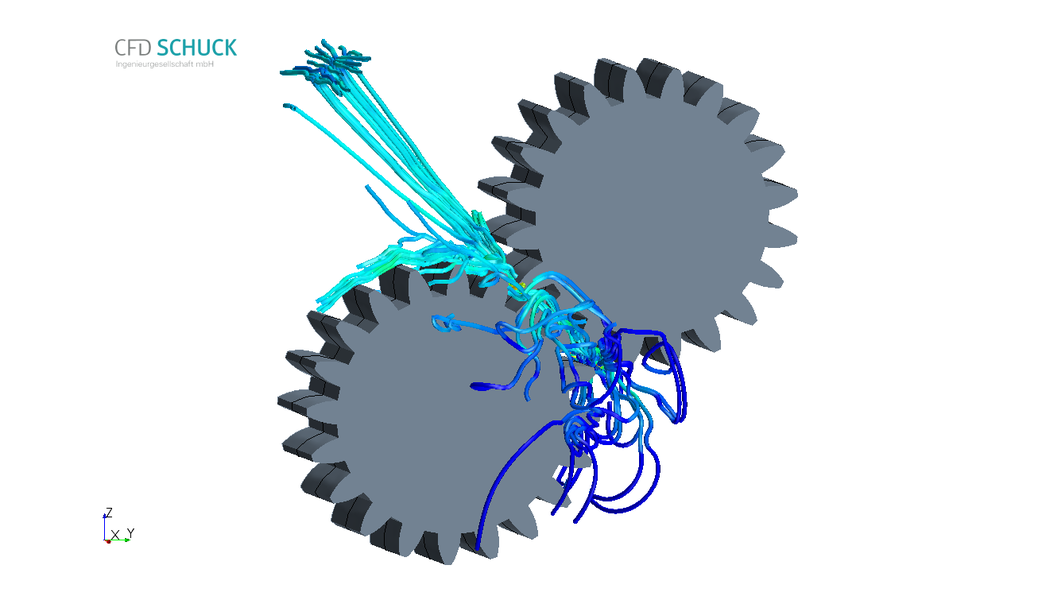
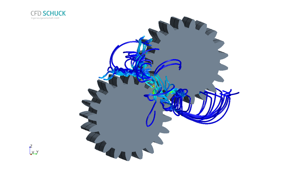
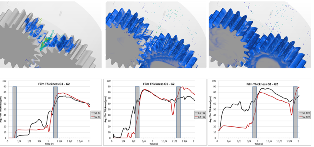
Prototype experiments do not give enough information on relevant details. A complete validation of the lubrication by prototype testing can hardly be done, especially at high rotation rates. On the other hand CFD simulations give detailed insight in the oil flow. Windage and splashing losses can be minimized. The oil flow can be analyzed and optimized in its interaction with oil injection and with the housing for different oil filling levels. Lubrication of flanks can be simulated. Film thickness and hydraulic torque and shear forces can be monitored to identify deficiencies causing transmission losses.
Even in between teeth or teeth in contact the results are numerically reliable.
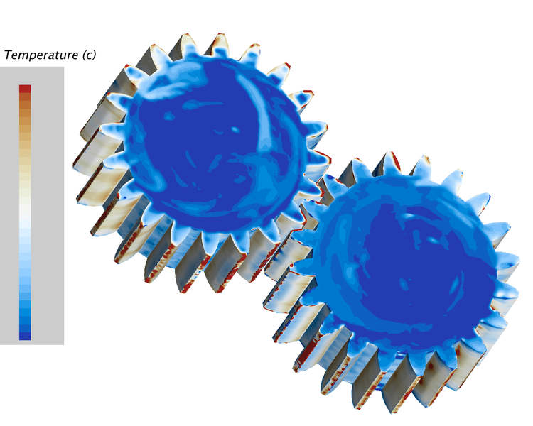
Heat management can be simulated. Heating of flanks by friction, heat conduction in gears, housing and oil can be analyzed. Oil viscosity as a function of temperature can be taken into account.
For more information read our article “Getriebesimulation – Möglichkeiten und Potentiale” published in Konstruktionspraxis Vogel, april 2016 (in german) and our contribution to the STAR Global Conference 2016 “High-end gearbox simulation: modelling gear contact with ‘zero gap interfaces’ on a multiphase spur-gear system“.


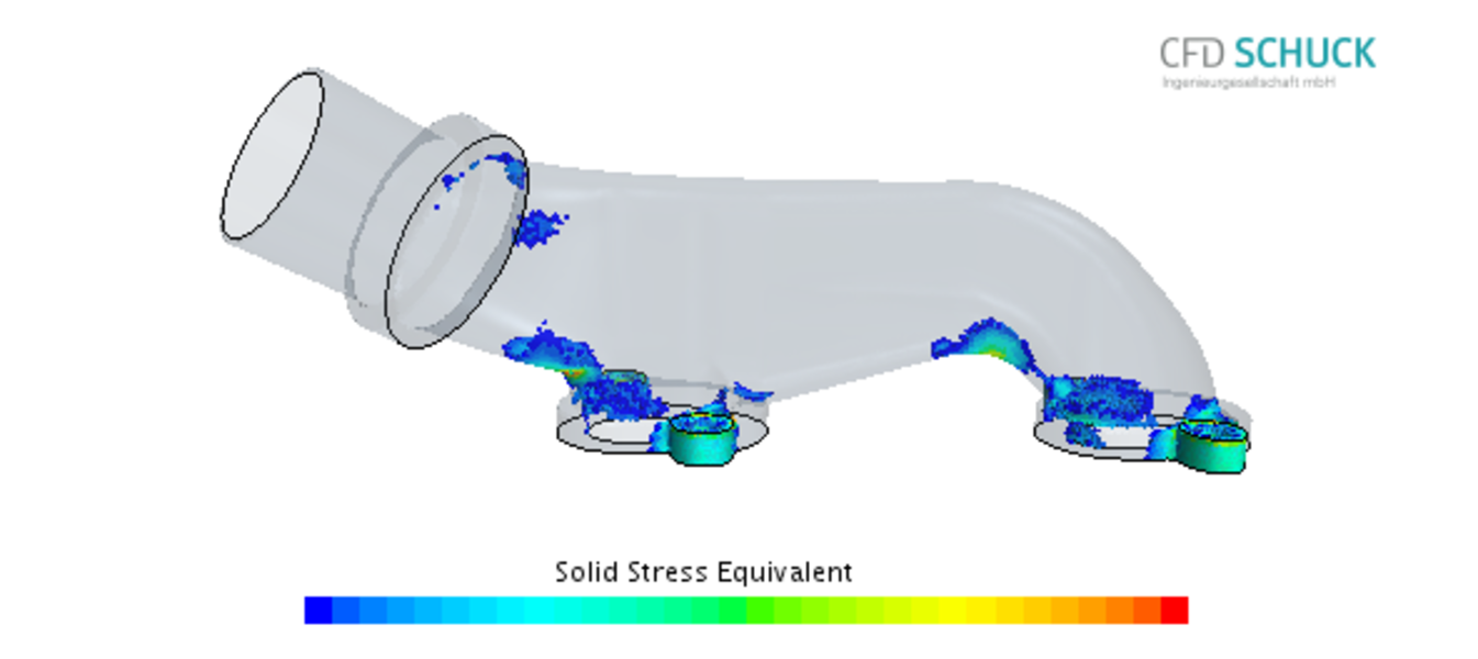
Great demands are made on the flow in water drains and fittings. Often measurements cannot adequatly capture the underlying phenomena. Maybe because water drains are implemented in a way that the position where sloshing or leakage occurs is not visible or such that the conditions under which these phenomena occur are unknown. Subsequent costs can be considerably high especially if sensitive electronics are involved.
Measurements in fittings are often compromising or can only be taken at very few postions. CFD-simulations are free oft these metering difficulties. Pressure loads on seals or sloshing phenomena in drains can be calculated with Volume-of-Fluid-simulations (VOF). Resulting geometry corrections can be tested virtually.
A purposeful reduction of pressure losses in fittings is possible. Self-cleaning can be improved by identification and elimination of dead spaces. Simulations with coupled fluid-structure-interaction (FSI) are suitable for diaphragm valves.

Standardise your simulations with your own specific simulation assistant
Often in one company there are many CFD simulations that strongly resemble each other. Sometimes there might be a change in geometry or in boundary conditions. But you always need a CFD expert to prepare the models and to define all relevant parameters correctly. This is often very expensive and time consuming. Nevertheless inaccuracies may occur that reduce the comparability of the results.
A customised simulation assistant (“flow wizard”) may help you. The simulation assistant is a plug-in for CCM+® that is designed especially for your demands. It comes with a graphical interface (GUI) that guides you through the simulation, if required from reading the CAD data to final results. Integration of simulation conditions provided in form of excel-data-sheets, the export of data for other analysis (e.g. FE) or the presentation directly in PowerPoint are examples of possible extra features.


With modern CFD-techniques it is possible to investigate the lubrication of complex gears at reasonable expense within a few days – illustrated here using the example of a rear axle differential. The oil distribution within the system can be monitored during adequately long periods. This allows the evaluation of complete oil circuits or for example the oil supply of bearings already in early design stages. Different operating conditions like start-up, stationary operation or even dynamic effects (e. g. inclination of gears during operation in mobile systems) can be simulated. This allows optimization already during the design phase.
Gears shown in this example were generated using the software KISSsoft (www.KISSsoft.AG).
Erfahren Sie mehr zu den verwendeten Verfahren: practical methods und zur Overset-Mesh-Methodology

Many challenges in the design of modern ventilation systems can be overcome using CFD simulations – ranging from controlled ventilation of assembly rooms according to the current standards to extraction systems for harmful substances in industrial plants and to clean room technology.
Compliance with the comfort criteria in assembly rooms can be controlled and appropriate measures can be taken. Examples for the investigations may be the combination of turbulence and flow velocity for different temperatures, vertical temperature differences or sufficient air exchange. For the latter the local residence time is examined to gain better insight into the ventilation situation as by the estimation of the global exchange rate.
Much stricter criteria have to be met in operational rooms. The current standards define, inter alia, a low-turbulent uni-directional air-flow for sufficient protection against particles and germs. Flow visualization using smoke affects the flow, CFD does not. Thus CFD makes it possible to examine realistic contamination scenarios.
Please contact us for further information.


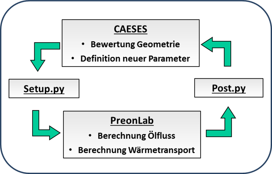
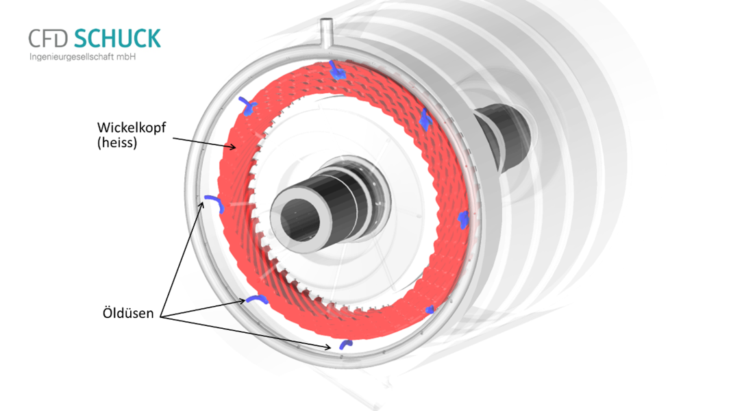
The cooling of electrical machines plays an important role in many questions. Modern simulation methods offer the possibility of designing cooling systems quickly and specifically for specific load cases. In the case of the oil spray cooling of a winding head, a method is now available that allows a quick and automated optimization by combining different software tools.
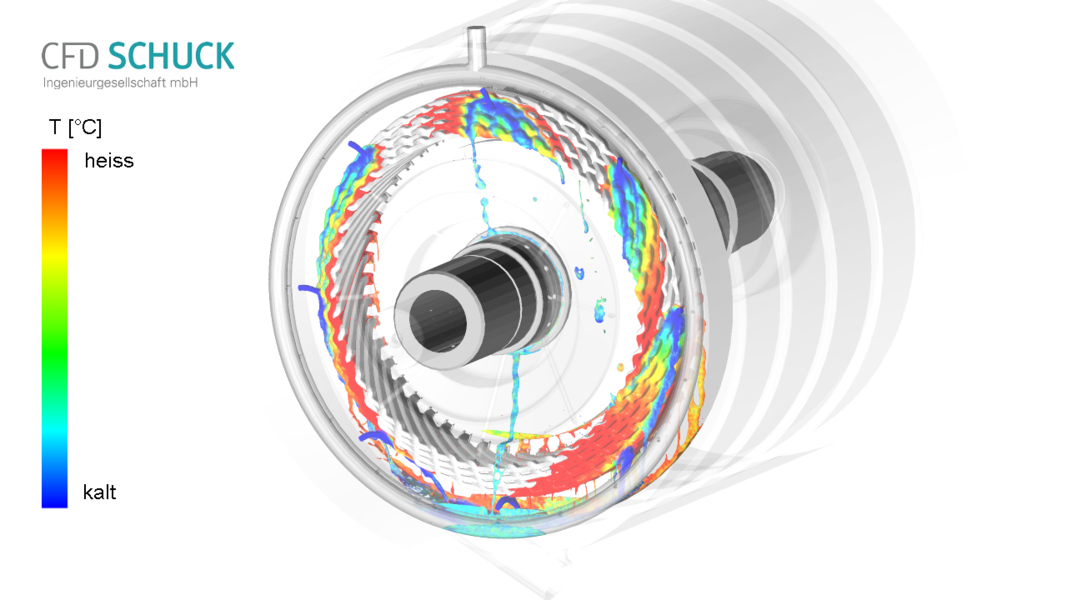
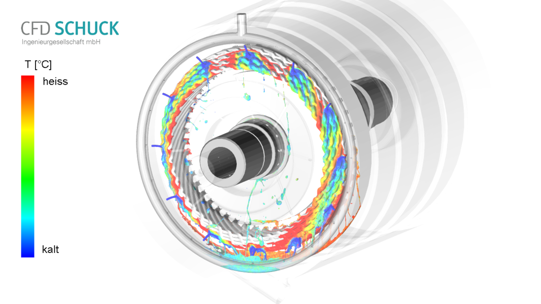
Optimization examines a variety of design options to determine a suitable configuration for good cooling . Typical design variables are the number and diameter of the nozzles, but also inclination and position relative to the winding head. Likewise, issues such as oil throughput or winding head temperature must also be assessed.
The SPH software PreonLab is used for CFD calculation of the oil spreading and cooling , the optimization is implemented with the software CAESES. In addition, Python routines are used for geometry generation, model setup, and evaluation. In our example (see video below) 40 design variants were examined in 3 days.
Further information can be found under spray cooling and SPH-Method. You can also contact us directly.